Every precision sound power level rests on two things measured before the machine arrives. An anechoic or hemi-anechoic room is only as free a field as its qualification shows, and a comparison method is only as right as the calibrated sound power of its reference sound source. ISO 26101 qualifies the room by the inverse square law, ISO 3745 holds that qualification to the criteria of the precision method in its Annex A, which Amendment 1:2017 rewrote from end to end to defer to ISO 26101, and ISO 6926 says what a reference sound source must do and how its sound power is calibrated. This guide covers the traverses and the deviations from the inverse square law, how the library fits the source strength and the mathematical origin, the verdict of the amended Annex A on a synthetic hemi-anechoic room, and a reference source calibrated on the 2 m hemisphere, judged against clause 5 and handed to a comparison method. The determinations themselves are in Sound Power by Pressure Methods and Sound Power in the Reverberation Room.
1. The inverse square law along a traverse (ISO 26101)
Section titled “1. The inverse square law along a traverse (ISO 26101)”A small source in a free field loses 6 dB for every doubling of distance. The divergence loss method of ISO 26101 clause 5.1 measures how far a real room departs from that: a microphone moves along straight traverses away from a test source, and at each point at the distance from the mathematical origin of the traverse the measured level is compared with the estimate of Formula (2),
and the deviation of Formula (4) is . If the source drifts by more than 0.2 dB while a traverse is measured (5.1.2.2 d)), a monitor microphone at a fixed position corrects each reading by Formula (1), . The room is qualified out to the largest distance at which every deviation, on every traverse and at every frequency, stays inside the limits of Table A.1:
| Room | Up to 630 Hz | 800 Hz to 5 000 Hz | From 6 300 Hz |
|---|---|---|---|
| Anechoic | ±1.5 dB | ±1.0 dB | ±1.5 dB |
| Hemi-anechoic | ±2.5 dB | ±2.0 dB | ±3.0 dB |
ISO 26101 Annex A and the amended ISO 3745 Annex A print the same cells.
A MicrophoneTraverse holds one traverse: the points as (x, y, z) in the
room frame, with z up and the reflecting plane of a hemi-anechoic room at
z = 0, the levels one column per test frequency, and optionally the monitor
readings and the background. MicrophoneTraverse.along lays one out along a
straight line. An exact inverse-square field is the first closed form: it
qualifies to the end of every traverse, with the level at 1 m and no
deviation anywhere.
import numpy as npfrom phonometry import emission
d = np.arange(0.30, 3.0001, 0.05)            # 5 cm steps from 0.3 m to 3 mexact = 90.0 - 20.0 * np.log10(d)             # 90 dB at 1 m, nothing reflectedpaths = [(1, 1, 1), (1, 1, 0.3), (0, 1, 0.5), (1, 0, 0.2), (-1, 0.5, 0.6)]traverses = [emission.MicrophoneTraverse.along(u, d, exact) for u in paths]fit = emission.inverse_square_law_deviations(    traverses, frequencies_hz=[1000.0], room="anechoic")print(round(fit.maximum_qualified_radius_m, 2))   # 3.0 mprint(fit.source_strength_db[:, 0].round(2))      # [90. 90. 90. 90. 90.]print(fit.largest_deviation_db.round(3))          # [0.]
The second closed form is a room with a known reflection. A fully reflecting wall 2.5 m ahead of the source, taken as an incoherent image, adds to the level at the distance , and the traverse qualifies for as long as the spread of that excess stays within twice the tolerance: at 1 kHz in an anechoic room, 2 dB. Solved for , the limit falls at 2.187 m, and the last point of a 5 cm grid before it is 2.15 m.
wall = 2.5 # a fully reflecting wall 2.5 m aheadd = np.arange(0.50, 2.4001, 0.05)excess = 10.0 * np.log10(1.0 + (d / (2.0 * wall - d)) ** 2)reflected = emission.MicrophoneTraverse.along( (1, 0, 0), d, 90.0 - 20.0 * np.log10(d) + excess)one = emission.inverse_square_law_deviations( [reflected], frequencies_hz=[1000.0], room="anechoic")print(round(float(one.traverse_radius_m[0, 0]), 2)) # 2.15 minside = d <= one.traverse_radius_m[0, 0]print(round(float(np.ptp(one.deviations_db[0][inside, 0])), 3)) # 1.903 dBprint(round(float(np.ptp(excess[inside])), 3)) # 1.903 dBprint(round(float(one.source_strength_db[0, 0]), 3)) # 91.005 dBprint(round(float(one.initial_source_strength_db[0, 0]), 3)) # 90.913 dBThe deviations spread over exactly the excess the wall adds, 1.903 dB, and
the the library fits, 91.005 dB, is not the starting value of Formula (3),
the mean of over every point, 90.913 dB, which
initial_source_strength_db reports beside it.
How the measurement goes
Section titled “How the measurement goes”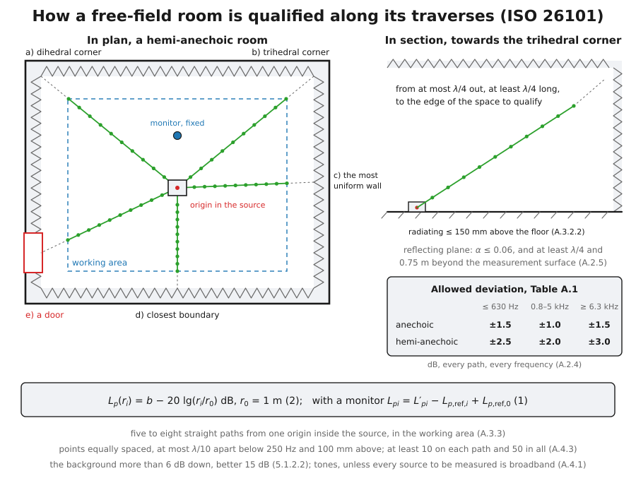
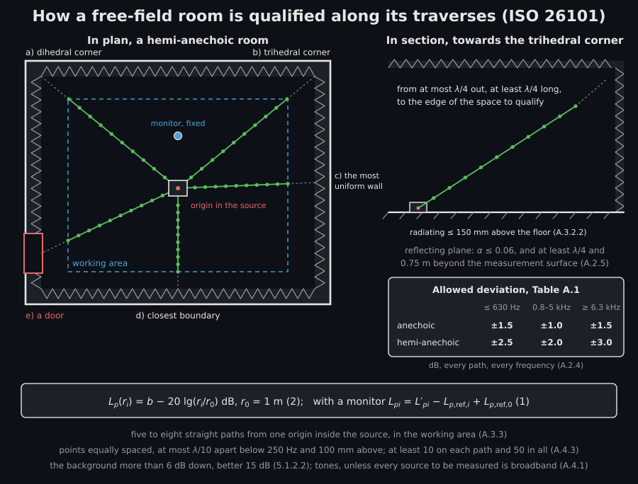
Place the test source where the sources under test will stand: at the centre
of an anechoic room, or on the reflecting plane of a hemi-anechoic one, as
close to it as its radiating area allows (A.3.2). Check that it radiates
evenly enough (Annex B, section 4 below). Lay out five to eight straight
traverses from one origin inside the source, in the part of the room used for
measurements (A.3.3): towards a dihedral corner, a trihedral corner, the
centre of the most uniform boundary, the closest boundary and whatever looks
worst, a door, a window, a ventilation opening, and name each path’s target
(targets=) so that the verdict can check all five are there. Run each one
from no more than a quarter of the wavelength of the lowest frequency out to
the boundary of the space to be qualified, at equally spaced points
(5.1.4.3). At every point record the level at each test frequency, the
monitor level beside it if the source might drift, and the background.
Qualify with tones unless every source to be measured is broadband
(A.4.1).
2. How the library fits b and the origin
Section titled “2. How the library fits b and the origin”Formula (2) leaves free: it “is adjusted to optimize the fit of the measured sound pressure levels into the tolerance range, to maximize the qualified distance from the test sound source”. NOTE 1 offers an iterative search starting from Formula (3), and no source prints either the search or a worked example, so the rule is designed here and stated. Write , so that . The points out to a distance fit inside for some exactly when the spread of their is at most , and that spread can only grow with . So the qualified distance of one traverse at one frequency is the last point of the longest run from the origin whose spread stays within , and every between and qualifies that run. The library takes the midpoint, , which leaves the same margin to both limits. No other qualifies a longer run, so there is nothing to iterate. When a traverse starts beyond the radius that every traverse meets, its is centred on its own qualified run.
The origin needs a rule of its own. ISO 26101 5.1.3.2 and the amended A.3.3
require every traverse to share one mathematical origin inside the physical
volume the test source occupies; the 2012 annex had instead fitted an offset
of the acoustic centre along each traverse, and A.1 d) warns that rooms
qualified that way may now qualify over less. Given origin_m, the distances
follow from the positions. Given source_box_m, the box the source occupies,
the library searches it for the origin with the largest radius of A.2.4. A
qualified distance ends either where a deviation leaves Table A.1, which the
room decides, or at the last point measured, which the measurement decides,
and moving the origin moves the distance to that last point without saying
anything about the room. So origins are compared by the distances at which
the room ends a run, a run that reaches its last point counting at the
distance of that point from the centre of the box, the same for every
origin; radii within the millimetre the search resolves count as equal. Ties
go to the origin whose curves fill the least of the Table A.1 band on
average, then to the one nearer the centre of the box. In an exact
inverse-square field the room ends no run, the curves are flat only from the
point the field diverges from, and the search returns that point. The search
is a lattice of five points per axis followed by a compass search that halves
its step down to 1 mm: deterministic, inside the box by construction and
never worse than the best lattice point.
3. A hemi-anechoic room
Section titled “3. A hemi-anechoic room”The example is a synthetic hemi-anechoic room, 8 m by 6 m by 5 m between the
wedge tips, whose hard floor is the reflecting plane and returns all of the
pressure. The source sits in a cavity in the floor, as A.3.2.2 recommends, so
the sound diverges from a point in the plane, 2 cm and −1 cm from the foot of
the source, and the source and its image in the floor coincide. Each wall and
the ceiling returns a coherent image, with its own image in the floor,
through the pressure reflection coefficient of its wedges, 0.30 at 100 Hz
falling to 0.05 at 10 kHz. Six traverses run from the foot of the source at
25 mm steps, one along each path A.3.3 asks for, each naming its target, and
one more towards the ceiling, and they are measured at the eleven frequencies
of A.2.3, which qualification_frequencies_hz lists: the one-third octave
bands below 125 Hz and above 4 000 Hz and the octave mid-band frequencies
between.
grid = emission.qualification_frequencies_hz()print(grid)   # [100. 125. 250. 500. 1000. 2000. 4000. 5000. 6300. 8000. 10000.]
walls = [(0, -4.0), (0, 4.0), (1, -3.0), (1, 3.0), (2, 5.0)]   # the wedge tipswedge = np.interp(np.log10(grid), np.log10([100, 125, 250, 500, 10000]),                  [0.30, 0.22, 0.12, 0.07, 0.05])centre = np.array([0.02, -0.01, 0.0])         # where the sound diverges from
def measured(points):    k = 2.0 * np.pi * grid / 343.0    images = [(centre, 1.0)]    for axis, plane in walls:        image = centre.copy()        image[axis] = 2.0 * plane - centre[axis]        images.append((image, wedge))    p = 0.0    for source, gain in images:        for mirrored in (source, source * (1.0, 1.0, -1.0)):   # and its floor image            r = np.linalg.norm(points - mirrored, axis=1)[:, None]            p = p + gain * np.exp(-1j * k * r) / r    return 88.0 + 20.0 * np.log10(np.abs(p))  # 94 dB at 1 m with the floor
paths = [   # name, where it points, the A.3.3 target it serves    ("dihedral corner", (4.0, 3.0, 2.5), ("dihedral corner",)),    ("trihedral corner", (-4.0, 3.0, 5.0), ("trihedral corner",)),    ("centre of a wall", (0.0, -3.0, 2.5), ("boundary centre",)),    ("nearest wall", (0.0, 3.0, 1.2), ("closest boundary",)),    ("door", (-4.0, -1.5, 1.0), ("unique features",)),    ("towards the ceiling", (1.5, 1.0, 4.0), ()),]d = np.arange(0.25, 3.0001, 0.025)            # 25 mm steps from 0.25 m to 3 mtraverses = []for name, towards, aims in paths:    unit = np.asarray(towards) / np.linalg.norm(towards)    traverses.append(emission.MicrophoneTraverse.along(        towards, d, measured(d[:, None] * unit), name=name, targets=aims,        background_levels_db=np.full(grid.size, 25.0)))
room = emission.inverse_square_law_deviations(    traverses, frequencies_hz=grid, room="hemi-anechoic",    source_box_m=((-0.05, -0.05, 0.0), (0.05, 0.05, 0.08)))print(room.origin_m.round(3))                 # [0.005 0.05  0.   ] mprint(room.band_radius_m.round(2))            # [2.76 2.95 2.95 ... 2.95] mprint(room.largest_deviation_db.round(1))     # [2.5 2.3 1.2 1.2 1.3 1.3 1.2 ...] dBprint(round(room.maximum_qualified_radius_m, 2))   # 2.76 m
foot = emission.inverse_square_law_deviations(    traverses, frequencies_hz=grid, room="hemi-anechoic", origin_m=(0.0, 0.0, 0.0))print(round(foot.maximum_qualified_radius_m, 2))   # 2.73 mat_centre = emission.inverse_square_law_deviations(    traverses, frequencies_hz=grid, room="hemi-anechoic", origin_m=centre)print(round(at_centre.maximum_qualified_radius_m, 2))   # 2.72 mprint(at_centre.largest_deviation_db.round(1))     # [2.4 1.7 1.2 0.8 0.7 0.6 0.6 ...] dB
Only 100 Hz is limited by the room: the wall straight ahead of the “centre of a wall” traverse returns 30 % of the pressure, and its deviation leaves the ±2.5 dB of Table A.1 at 2.76 m. At every other frequency the traverses qualify to their last point, 2.95 m from the origin the search chose, which sits on the floor at the edge of the box where the 100 Hz run is longest. Held at the foot of the source instead, the same data qualify to 2.73 m. Held at the point the sound really diverges from, 6 cm from the origin the search chose, the deviations above 500 Hz halve, from 1.1 to 1.3 dB to 0.6 to 0.7 dB, but the room qualifies only to 2.72 m: the search trades margin inside the tolerance for distance, which is what Formula (2) asks of it, and the margin it gives up weighs most at the points nearest the source. The floor adds no ripple of its own, because the acoustic centre lies in its plane. Raised 3 cm above it, the source and its image would interfere all along the traverses, and the room would qualify to only 0.44 m, held there by 4 kHz and 6.3 kHz, with 8 kHz not far behind at 0.72 m: that is why A.3.2.2 asks for the centre within a tenth of a wavelength of the floor.
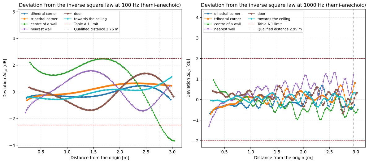
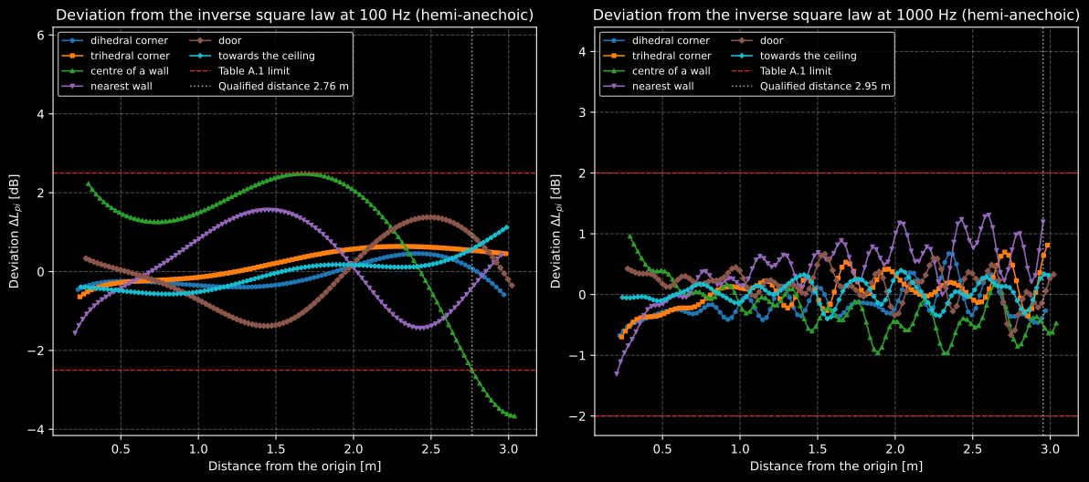
The deviations along the six traverses at 100 Hz and at 1 kHz. At 100 Hz the reflection from the wall ahead of the “centre of a wall” traverse builds a standing pattern of a few metres’ period that crosses the lower limit at 2.76 m, and that point sets the radius of the whole room. At 1 kHz the ripple is fast and small, and every traverse qualifies to its end.
Show the code for this figure
import matplotlib.pyplot as plt
# room is the result computed above.fig, (low, high) = plt.subplots(1, 2, figsize=(12.5, 5.6))room.plot(ax=low, frequency_hz=100.0)room.plot(ax=high, frequency_hz=1000.0)plt.show()
The fitting functions
Section titled “The fitting functions”| Function | Clause | Returns | Notes |
|---|---|---|---|
MicrophoneTraverse(positions_m, levels_db, monitor_levels_db=None, background_levels_db=None, name="", targets=()) | 5.1.3.2, A.3.3 | one traverse | nan marks a point not measured at a frequency, which is how a spacing that changes with frequency is written; targets names what the path is selected towards among "dihedral corner", "trihedral corner", "boundary centre", "closest boundary" and "unique features" |
MicrophoneTraverse.along(direction, distances_m, levels_db, *, start_m=(0, 0, 0), ...) | 5.1.3.2 | one traverse | Laid out along a straight line |
inverse_square_law_deviations(traverses, *, frequencies_hz, room, origin_m=None, source_box_m=None) | Formulae (1) to (4) | InverseSquareLawResult | One call per test source; origin_m or source_box_m, not both |
inverse_square_law_tolerance_db(frequencies_hz, *, room) | Table A.1 | limit per band [dB] | A tone is read in the one-third octave band that contains it |
qualification_frequencies_hz(low_hz=100.0, high_hz=10000.0) | A.2.3 | frequencies [Hz] | Eleven over the minimum range |
The result carries the distances, the corrected levels, per traverse and
frequency beside the starting value of Formula (3), the deviations, the
qualified distance of each traverse (traverse_radius_m), of each frequency
on every traverse (band_radius_m) and of the whole room
(maximum_qualified_radius_m), and the largest deviation within each band’s
radius.
4. The verdict of the amended Annex A
Section titled “4. The verdict of the amended Annex A”check_free_field holds one or more fitted sources to the Annex A that
ISO 3745:2012/Amd.1:2017 wrote, and to the clauses of ISO 26101 it defers to:
- Deviations and radius (A.2.2, A.2.4): the maximum qualified radius is the smallest qualified distance over every traverse and every evaluated frequency, and the other requirements are judged within it.
- Frequencies (A.2.3): 100 Hz to 10 000 Hz at least. Anything less is a
reduced range, and
conforming_range_hzgives the widest contiguous run over which every judged requirement holds, the range a report may state “in conformity” with, never “in full conformity”. - Traverses (A.3.3): five to eight, towards all five targets a) to e) as
the traverses name them, in the working area of the room, a declaration
(
paths_in_working_area) since the positions cannot tell, and in a hemi-anechoic room every one within the 20° to 80° from the vertical over which the source directionality was measured. A path is judged by its direction, the line from its first to its last point within the radius. - Points (A.4.3): at least 10 on each traverse and 50 in total within the radius, equally spaced at each frequency, and spaced at most a tenth of a wavelength below 250 Hz and 100 mm above. Points added between two of the grid near a peak deviation, as the last paragraph of A.4.3 recommends, do not break the grid; the next point of the grid has to lie within a tenth of the median gap of where one step would put it, a tolerance no source prints.
- Resolution and length of ISO 26101 (A.2.4, which cites 5.1.4.3 and A.4.3): a start no farther than a quarter wavelength of the lowest frequency and a run at least that long, and a spacing of at most a tenth of a wavelength below 1 kHz and 25 mm above. Neither spacing rule says which side holds in the band that contains its edge frequency, 250 Hz or 1 kHz; the verdict holds that band to the stricter of the two.
- Background (ISO 26101 5.1.2.2 c)): every point at least 6 dB above it.
- Test source (A.3.1, ISO 26101 Annex B):
verify_source_directionalityreads the 32 positions of a 1.5 m hemisphere (64 of a sphere in an anechoic room) thatdirectionality_positionsreturns, and holds the largest deviation from the mean level in each band to Table B.1. - Reflecting plane (A.2.5): an absorption coefficient of at most 0.06, and a plane that extends at least a quarter wavelength and 0.75 m beyond the projection of the measurement surface.
A requirement whose data were not given is listed in not_judged, and
passes stays False until it is judged.
rows = np.arange(32)[:, None]bands = np.arange(grid.size)[None, :]source = emission.verify_source_directionality(    80.0 + 0.4 * np.sin(0.7 * rows + bands) * (1.0 + bands / 10.0),    frequencies_hz=grid, room="hemi-anechoic")print(source.passes)                                         # True
check = emission.check_free_field(    room, bandwidth="discrete-frequency", source_directionality=source,    measurement_radius_m=1.5, paths_in_working_area=True,    reflecting_plane_absorption_coefficient=0.02, reflecting_plane_margin_m=1.2)print(check.passes, round(check.maximum_qualified_radius_m, 2))   # True 2.76print(check.full_frequency_range, check.path_angles_met)          # True Trueprint(check.path_targets_met, bool(check.equal_spacing_met.all()))  # True True
unjudged = emission.check_free_field(room, bandwidth="discrete-frequency")print(unjudged.passes, unjudged.not_judged)# False ('source directionality', 'reflecting plane', 'working area')
The room qualifies in full conformity for measurement radii up to 2.76 m,
discrete-frequency and therefore for tonal sources as well as broadband ones
(A.4.1). A qualification made with broadband noise in one-third octave bands
is given bandwidth="broadband", and holds only for broadband sources.
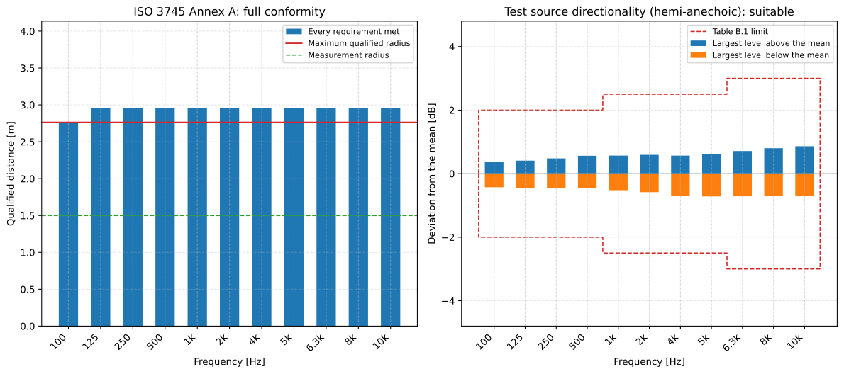
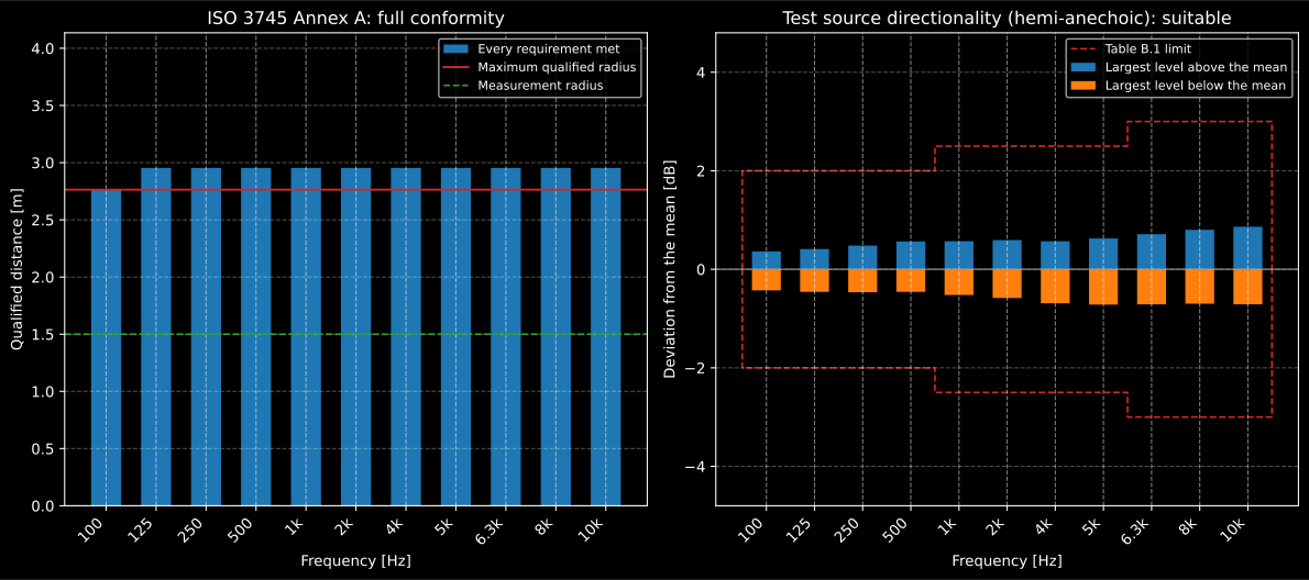
On the left, the verdict: every frequency meets every requirement, and the 100 Hz band sets the maximum qualified radius. On the right, the test source, measured at the 32 positions of Annex B, keeps well inside Table B.1 in every band.
Show the code for this figure
import matplotlib.pyplot as plt
# check and source are the results computed above.fig, (left, right) = plt.subplots(1, 2, figsize=(12.5, 5.6))check.plot(ax=left)source.plot(ax=right)plt.show()
Two resolutions for one traverse
Section titled “Two resolutions for one traverse”A.2.4 asks every traverse for the spatial resolution of ISO 26101 A.4.3, a
tenth of a wavelength below 1 kHz and 25 mm above, while the amendment’s own
A.4.3 sets a tenth of a wavelength below 250 Hz and 100 mm above, and its last
paragraph presupposes 100 mm traverses. Both are printed with “shall”, so the
verdict judges both and reports each: spacing_met for the amended A.4.3 and
iso26101_spacing_met for the resolution A.2.4 cites. The same room sampled
every 100 mm meets the first everywhere and the second only up to 250 Hz,
where a tenth of a wavelength is still longer than 100 mm, and qualifies over
a reduced range:
coarse = [emission.MicrophoneTraverse( positions_m=t.positions_m[::4], levels_db=t.levels_db[::4], background_levels_db=t.background_levels_db[::4], name=t.name, targets=t.targets) for t in traverses]room100 = emission.inverse_square_law_deviations( coarse, frequencies_hz=grid, room="hemi-anechoic", source_box_m=((-0.05, -0.05, 0.0), (0.05, 0.05, 0.08)))check100 = emission.check_free_field( room100, bandwidth="discrete-frequency", source_directionality=source, measurement_radius_m=1.5, paths_in_working_area=True, reflecting_plane_absorption_coefficient=0.02, reflecting_plane_margin_m=1.2)print(check100.passes, bool(check100.spacing_met.all())) # False Trueprint(check100.iso26101_spacing_met[:4]) # [ True True True False]print(check100.conforming_range_hz, round(check100.conforming_radius_m, 2))# (100.0, 250.0) 2.71The inconsistency is in the errata registry. A laboratory that takes A.4.3 as the rule of the annex reads the two flags and decides.
The qualification in a determination
Section titled “The qualification in a determination”sound_power_anechoic takes the verdict as room_qualification: the room
type must match the surface, and a SoundPowerWarning says when the room is
not qualified, when the measurement radius lies beyond the qualified one, or
when a band lies outside the qualified range.
import warnings
levels = np.full((20, 3), 70.0)with warnings.catch_warnings(record=True) as caught:    warnings.simplefilter("always")    emission.sound_power_anechoic(        levels, "hemisphere", radius=2.8, frequencies=[500.0, 1000.0, 2000.0],        room_qualification=check)print(caught[0].message)# The measurement radius 2.8 m lies beyond the qualified radius 2.76 m# (ISO 3745:2012/Amd.1:2017, A.2.4).
The verdict functions
Section titled “The verdict functions”| Function | Clause | Returns | Notes |
|---|---|---|---|
check_free_field(results, *, bandwidth, source_directionality=None, measurement_radius_m=None, reflecting_plane_absorption_coefficient=None, reflecting_plane_margin_m=None, paths_in_working_area=None, speed_of_sound=343.0) | Annex A as amended | FreeFieldCheck | One result per test source, their frequencies disjoint; what was not given is in not_judged |
verify_source_directionality(levels_db, *, frequencies_hz, room) | ISO 26101 Annex B | SourceDirectionalityResult | 32 or 64 positions, one column per band |
directionality_positions(room, *, radius_m=1.5) | ISO 26101 B.3.2 | positions [m] | Elevation from the vertical, azimuth in 45° steps |
directionality_tolerance_db(frequencies_hz, *, room) | Table B.1 | limit per band [dB] | 5 dB above 10 kHz |
5. A reference sound source (ISO 6926)
Section titled “5. A reference sound source (ISO 6926)”A reference sound source is the yardstick of every comparison method: ISO 3741 in a reverberation room, ISO 3743-1 and ISO 3743-2 in a small test room, ISO 3747 in situ, ISO 9295 in the 16 kHz octave. ISO 6926 clause 5 says what it must do. Its output is steady: the standard deviation under repeatability conditions of three repeated sound power levels or five sound pressure levels, Formula (1), about their energy average, does not exceed Table 1, 0.8 dB from 50 Hz to 80 Hz, 0.4 dB from 100 Hz to 160 Hz and 0.2 dB from 200 Hz to 20 kHz, and over the range of its electrical or mechanical supply its manufacturer declares, the line voltage say, no band moves by more than 0.3 dB either way (5.2). Its spectrum is broadband: from 100 Hz to 10 000 Hz every one-third octave band lies within a range of 12 dB and within 3 dB of its neighbours, 16 dB and 4 dB over a range extended beyond it (5.4). Its directivity index does not exceed 6 dB in any band from 100 Hz to 10 000 Hz (5.5), unless it is labelled for reverberation rooms only. And it is recalibrated when a band has moved by more than 2.83 times Table 1 between two checks (5.6).
Clause 8 calibrates it in a hemi-anechoic room qualified for broadband noise by ISO 3745 Annex A (8.1), on the reflecting plane, over a hemisphere of radius 2 m (8.2.1). Formula (2) carries the surface level to the sound power level under the reference conditions of clause 4, 23.0 °C and 101.325 kPa:
with , K, the radiation impedance correction from the manufacturer or from the informative Annex A, and the air absorption with . The example is a fan-type source calibrated at the 20 fixed positions of ISO 3745 Annex E on the 2 m hemisphere, at 20 °C, 45 % and 98.6 kPa, radiating a little more upwards at high frequencies.
from phonometry import environment
thirds = np.array([100.0, 125.0, 160.0, 200.0, 250.0, 315.0, 400.0, 500.0, 630.0,                   800.0, 1000.0, 1250.0, 1600.0, 2000.0, 2500.0, 3150.0, 4000.0,                   5000.0, 6300.0, 8000.0, 10000.0])source_lw = np.array([86.0, 86.8, 87.5, 88.1, 88.4, 88.6, 88.7, 88.6, 88.4, 88.1,                      87.7, 87.2, 86.6, 85.9, 85.1, 84.2, 83.2, 82.1, 80.9, 79.6,                      78.2])positions = emission.precision_positions("hemisphere", radius=2.0, count=20)upward = positions[:, 2:3] / 2.0 - 0.5pattern = 4.0 * upward * np.sqrt(thirds / 10000.0)[None, :]alpha = environment.air_attenuation(    thirds, temperature_c=20.0, relative_humidity_percent=45.0,    atmospheric_pressure_kpa=98.6)levels = (source_lw[None, :] - 10.0 * np.log10(2.0 * np.pi * 2.0**2)          + pattern - 2.0 * alpha[None, :])
air = emission.CalibrationConditions(    temperature_c=20.0, static_pressure_kpa=98.6, air_absorption_db_per_m=alpha)calibration = emission.reference_source_calibration(    levels, frequencies_hz=thirds, arrangement="fixed", conditions=air)print(calibration.sound_power_level_db[[0, 10, 20]].round(2))  # [86.06 87.77 78.41] dBprint(round(calibration.c1_db, 3), calibration.c2_db[0].round(3))   # -0.031 0.087print(calibration.c3_db[[0, 10, 20]].round(3))                 # [0.001 0.009 0.351] dBprint(calibration.expanded_uncertainty_db[[0, 3, 16]].round(2))    # [1.57 0.98 1.96] dBprint(round(calibration.sound_power_level_a_db, 1))            # 97.6 dB
CalibrationConditions carries the air of the calibration: its temperature
and static pressure enter and , and its enters .
Without it the calibration is made at the reference conditions of clause 4,
with no air absorption. The surface is averaged as ISO 3745 averages it, through
sound_power_anechoic. and nearly cancel at this pressure and
temperature, leaving 0.06 dB; here is Formula (A.5) of Annex A for a source whose
radiation is unknown,
with K, and c2_db takes the manufacturer’s value instead,
which 8.4 prefers. reaches 0.35 dB at 10 kHz over the 2 m path. The
expanded uncertainty is with from the Table 2
column of the arrangement, 0.8 dB from 100 Hz to 160 Hz, 0.5 dB from 200 Hz
to 3 150 Hz and 1.0 dB above for the fixed positions. At 50 Hz to 80 Hz,
Annex B replaces the pressure levels by sound intensity levels when the two
agree within Table B.1 from 50 Hz to 315 Hz (intensity_sound_power_level_db).
verify_reference_sound_source then judges clause 5. A calibration brings its
bands, levels and directivity indices; the repetitions of 8.3.3 and the
largest change of each band over the declared supply range are passed
alongside, and a source calibrated elsewhere, in a reverberation room by
clause 9 for instance, passes its levels and frequencies instead. What is not
given is listed in not_judged, and the source does not comply until it is
judged.
jitter = np.array([[0.05], [-0.08], [0.04]]) * np.where(thirds < 200.0, 3.0, 1.0)supply = 0.12 + 0.06 * np.cos(np.arange(thirds.size) / 3.0)   # over +-10 % line voltageverdict = emission.verify_reference_sound_source(    calibration, repeated_levels_db=calibration.sound_power_level_db[None, :] + jitter,    supply_variation_db=supply)print(verdict.passes)                                        # Trueprint(round(verdict.core_range_db, 2), verdict.adjacent_step_db.max().round(2))# 10.35 1.37print(verdict.repeatability_db[[0, 4]].round(3), verdict.repeatability_limit_db[[0, 4]])# [0.217 0.072] [0.4 0.2]print(verdict.supply_variation_db.max().round(2), verdict.supply_met)   # 0.18 True
drift = emission.verify_reference_source_drift(    calibration.sound_power_level_db,    calibration.sound_power_level_db + np.where(thirds < 160.0, 1.2, 0.3),    frequencies_hz=thirds)print(drift.passes, drift.recalibration_required)            # False True
The source spans 10.35 dB from 100 Hz to 10 000 Hz with steps of at most 1.37 dB, repeats to 0.217 dB at 100 Hz against 0.4 dB, moves by at most 0.18 dB over its supply range against 0.3 dB, and its highest directivity index, 1.75 dB at 10 kHz, is far from 6 dB. A later check that finds the two lowest bands 1.2 dB higher calls for recalibration, since 2.83 times 0.4 dB is 1.13 dB.
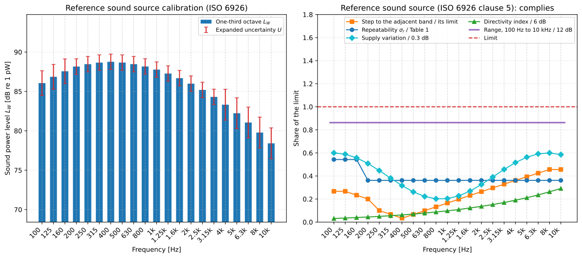
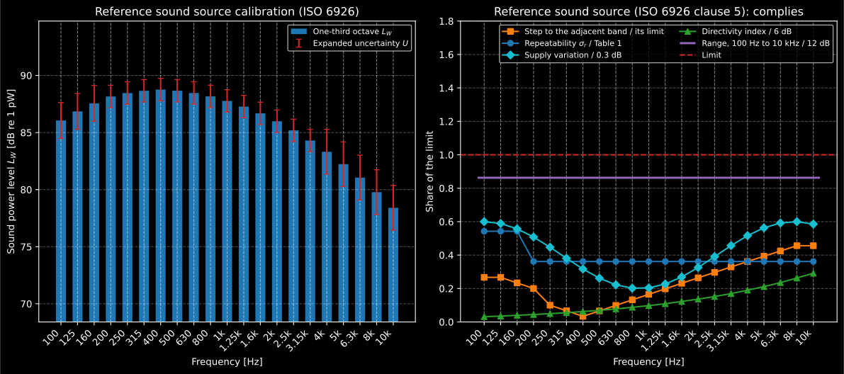
On the left, the calibrated levels with their expanded uncertainty from Table 2. On the right, each requirement of clause 5 as a share of its limit: anything below 1 complies. The requirements of one band are curves, and the range of 5.4, which holds over many bands at once, is a line across them; it is the one closest to its limit. The directivity index grows with frequency, as the source beams more upwards, and so does the step between neighbouring bands as the spectrum falls away.
Show the code for this figure
import matplotlib.pyplot as plt
# calibration and verdict are the results computed above.fig, (left, right) = plt.subplots(1, 2, figsize=(12.5, 5.6))calibration.plot(ax=left)verdict.plot(ax=right)plt.show()
The calibration in a comparison method
Section titled “The calibration in a comparison method”Every comparison method accepts the calibration where it accepts the levels,
and reads the bands it needs: sound_power_comparison and
sound_energy_comparison (ISO 3741) and high_frequency_sound_power_comparison
(ISO 9295, broadband only) in one-third octaves, sound_power_hard_walled
and sound_energy_hard_walled (ISO 3743-1),
sound_power_special_room_comparison (ISO 3743-2), sound_power_in_situ and
sound_energy_in_situ (ISO 3747) in octaves, each the energy sum of its
three one-third octave bands. The suitability evaluation of ISO 3743-2 6.7,
check_special_room_suitability, takes it as the calibration the room is
judged against, in octaves too. sound_power_level_at reads it directly.
The calibration holds under the reference conditions, and is what
carried the power the source radiated during the calibration there. ISO 3741
asks for “corrected to the meteorological conditions at
the time of test” (Formulae (21) and (31)), ISO 9295 corrects as ISO 3741
does, and both parts of ISO 3743 give “under the meteorological
conditions which occurred at the time and place of the test” (Annex A of
Part 1, Annex E of Part 2), so those methods read the calibration at the
temperature and pressure of the test, as with evaluated
there by the formula the calibration used, which 8.4 asks the user to share
with the laboratory.
ISO 3747 corrects the measured levels of the reference source to its
calibration by the manufacturer’s specifications instead (Equation (9)), and
reads the calibrated levels as they are. A calibration made with the
manufacturer’s c2_db cannot be read at a test, since only the manufacturer
gives there, and says so.
rng = np.random.default_rng(1)lp_rss = 70.0 + rng.normal(0.0, 0.4, (6, thirds.size)) # six positionslp_st = lp_rss + 4.0 # 4 dB louder everywheretest = emission.sound_power_comparison(lp_st, lp_rss, calibration, frequencies=thirds, temperature_c=18.0, static_pressure_kpa=96.0)print(test.sound_power_level[[0, 10, 20]].round(2)) # [90. 91.72 82.36] dBprint(calibration.sound_power_level_at( [1000.0], temperature_c=18.0, static_pressure_kpa=96.0).round(2)) # [87.59] dBprint(calibration.sound_power_level_at( [125.0, 1000.0, 8000.0], bandwidth="octave").round(2)) # [91.64 92.52 84.65] dBAt 18 °C and 96 kPa the source radiates 0.18 dB less than it would under the reference conditions, dB at 1 kHz, and ISO 3741’s own , 0.13 dB, carries the result of the source under test back to them.
The reference-source functions
Section titled “The reference-source functions”| Function | Clause | Returns | Notes |
|---|---|---|---|
reference_source_calibration(levels_db, *, frequencies_hz, arrangement, background_levels_db=None, maximum_levels_db=None, conditions=None, radiation="unknown", knee_frequency_hz=None, c2_db=None, intensity_sound_power_level_db=None, room_qualification=None, coverage_factor=1.96) | 8, Formula (2) | ReferenceSourceCalibration | arrangement is "paths" or "fixed", the column of Table 2; room_qualification warns when the room does not cover the bands at 2 m (8.1) |
CalibrationConditions(*, temperature_c=23.0, static_pressure_kpa=101.325, air_absorption_db_per_m=None) | 4, 8.4 | the air of Formula (2) | Temperature and static pressure for and , per band for |
ReferenceSourceCalibration.sound_power_level_at(frequencies_hz, *, bandwidth="one-third-octave", temperature_c=None, static_pressure_kpa=None) | 8.4 | per band [dB] | With the conditions of a test, there |
verify_reference_sound_source(calibration, *, frequencies_hz=None, repeated_levels_db=None, supply_variation_db=None, directivity_index_db=None, reverberation_rooms_only=False) | 5.2, 5.4, 5.5 | ReferenceSoundSourceVerdict | Three sound power or five sound pressure repetitions; the largest change over the declared supply range |
verify_reference_source_drift(reference_levels_db, latest_levels_db, *, frequencies_hz) | 5.6 | ReferenceSourceDriftResult | 2.83 times Table 1 |
repeatability_standard_deviation(levels_db) | Formula (1) | per band [dB] | About the energy average |
radiation_impedance_correction(*, temperature_c=23.0, static_pressure_kpa=101.325, radiation="unknown", frequencies_hz=None, knee_frequency_hz=None) | Annex A | [dB] | Monopole, aerodynamic dipole or unknown |
knee_frequency(d0_m, *, speed_of_sound=343.0) | Formula (A.1) | [Hz] | |
reference_source_reproducibility_db(frequencies_hz, *, environment, arrangement=None, bandwidth="one-third-octave") | Table 2 | per band [dB] | The one-third octave and octave columns read separately |
Formula (A.1) has a defect of its own: Annex A defines its as half the
characteristic source dimension of ISO 3745, which ISO 3745 3.14 already
defines as the distance from the origin to the farthest corner of the
reference box. knee_frequency takes the length that enters the formula, and
the errata registry has the details.
What this guide covers
Section titled “What this guide covers”Covered
The ISO 26101:2017 divergence loss method with the criteria of the Annex A that ISO 3745:2012/Amd.1:2017 wrote: the monitor correction of Formula (1), the estimate and deviations of Formulae (2) and (4) with the starting value of Formula (3), the source strength fitted as the midpoint of its admissible interval, the mathematical origin fixed or searched inside the box the test source occupies (5.1.3.2, A.3.3), the limits of Table A.1 for anechoic and hemi-anechoic rooms, the frequencies of A.2.3 and the reduced range, the maximum qualified radius of A.2.4, the traverse count, the targets a) to e), the working area and the path angles of A.3.3, the points, equal spacing and largest spacing of A.4.3 beside the spatial resolution and traverse length of ISO 26101 A.4.3 and 5.1.4.3, the 6 dB background margin of 5.1.2.2 c), the test source directionality of Annex B and Table B.1, the reflecting plane of A.2.5, and the verdict as
sound_power_anechoicconsumes it. ISO 6926:2016: the requirements of clause 5 (Table 1 and the supply variation of 5.2, the spectrum of 5.4, the directivity index of 5.5 and the recalibration of 5.6), the calibration in a hemi-anechoic room of clause 8 with Formula (2), , the of Annex A, and the Annex B intensity bands, the reproducibility of Table 2, and the calibration as every comparison method consumes it, read at the conditions of the test where ISO 3741 and ISO 3743 ask for it.Not covered
No source prints a worked example, so the fit is anchored in closed forms and in the printed tables, and the rule that fits and the origin, the tolerance on equal spacing and the band that holds the edge of a spacing rule are this library’s design (sections 2 and 4). The working area and the declared range of the supply are taken as declared, and a calibration made with the manufacturer’s is not carried to the conditions of a test. The continuous traverse of 5.1.4.3 is taken as the points derived from its record; the qualification of a room for a specific source by the alternative of ISO 3745 Annex B, the measurement uncertainty of ISO 26101 5.1.6, which A.2.2 excludes, and the atmospheric correction of ISO 26101 NOTE 2 are not performed. The ISO 6926 calibration in a reverberation room (clause 9) is taken as its result, the levels a verdict can judge; the sound intensity of Annex B is taken as measured by ISO 9614-3.
References
Section titled “References”- International Organization for Standardization. (2016). Acoustics — Requirements for the performance and calibration of reference sound sources used for the determination of sound power levels (ISO 6926:2016). Third edition. The performance requirements of clause 5 with Table 1, the calibration in a hemi-anechoic room of clause 8 with Formulae (1) and (2), Table 2, Annex A on C2 and Annex B on sound intensity at low frequencies. The Spanish adoption UNE-EN ISO 6926:2016 was read for cross-checks.
- International Organization for Standardization. (2017). Acoustics — Determination of sound power levels and sound energy levels of noise sources using sound pressure — Precision methods for anechoic rooms and hemi-anechoic rooms — Amendment 1 (ISO 3745:2012/Amd.1:2017). Replaces Annex A of ISO 3745:2012 with one that defers to ISO 26101:2017, 5.1: Table A.1, the frequency range of A.2.3, the maximum qualified radius of A.2.4, the reflecting plane of A.2.5, the traverse paths of A.3.3 and the spatial resolution of A.4.3.
- International Organization for Standardization. (2017). Acoustics — Test methods for the qualification of free-field environments (ISO 26101:2017). The divergence loss method of clause 5.1: Formulae (1) to (4), the traverses of 5.1.3.2, the traverse length of 5.1.4.3, Table A.1, the spatial resolution of A.4.3 and the test source directionality of Annex B with Table B.1.