Audio-Frequency Induction Loops (IEC 60118-4)
Standards: IEC 60118IEC 62489E DIN EN 62489-1/A2IEC 60028Key references: Grover 1946
A hearing aid switched to its telecoil picks up a magnetic field instead of sound: the voice of a talker, fed to an amplifier that drives a current round a loop of wire laid in the floor, reaches the listener without the reverberation and the noise of the room in between. Two IEC standards divide the work. IEC 60118-4 says what field the installed system has to produce, where, and with how little noise, and how an installer shows that it does. IEC 62489-1 says how the manufacturer of each component, the amplifier, the loop as a load and the neck loop, measures and states what it does. This guide follows both: the reference level and its units, the field a loop produces, the loop as the load an amplifier drives, the test signals and the meter, the verdicts on a room, a refuge and a counter, the overload test of Amendment 1, and the amplifier and the neck loop.
1. The reference and the level (IEC 60118-4 3.1, 4.3, E.2, E.6)
Section titled “1. The reference and the level (IEC 60118-4 3.1, 4.3, E.2, E.6)”Every level in the standard is referred to a magnetic field strength of 400 mA/m, 0 dB: . The reference is chosen so that a long-term average of −12 dB, 100 mA/m, gives the hearing aid the same acoustic output as a sound pressure level of 70 dB at its microphone (4.3), while 0 dB itself is the maximum field strength of 8.2.7, read with a 1 kHz sine or the combi signal on the true-RMS meter. The field strength is in amperes per metre because it is proportional to the current in the loop and falls with distance from the conductor; in air the flux density is , so 400 mA/m is about 0.5 µT (E.6).
A telecoil is a small coil on a ferrite rod, and it responds to the component of the field along its axis: , 3 dB down at 45° and 9.3 dB down at 70° (E.2, Figure E.6). A telecoil in a hearing aid worn upright is vertical, which is why every measurement of IEC 60118-4 is made with the pick-up coil vertical unless the users kneel or lie (8.1), and why the horizontal loop in the floor is the usual design.
import numpy as npfrom phonometry import electroacoustics
print(electroacoustics.field_strength_level([0.4, 0.1]).round(2))    # [  0.   -12.04]print(electroacoustics.field_strength([-3.0, 3.0]).round(3))         # [0.283 0.565] A/mprint(round(float(electroacoustics.magnetic_flux_density(0.4)) * 1e6, 3))  # 0.503 µTprint(electroacoustics.telecoil_response([45.0, 70.0]).round(2))     # [-3.01 -9.32]
The ±3 dB window of 10.2 as amended is printed as “283 mA/m to 566 mA/m”: those are and , a factor of read as 3 dB; exactly ±3 dB is 283 mA/m to 565 mA/m. E.6 prints the flux density of 1 A/m as 1.256 µT where rounds to 1.257 µT, a slip the errata register records.
2. The field of a loop (IEC 60118-4 Annex E, IEC 62489-1 5.4.10)
Section titled “2. The field of a loop (IEC 60118-4 Annex E, IEC 62489-1 5.4.10)”A current round a loop of turns produces a field proportional to everywhere. IEC 60118-4 E.1 gives the one closed form it uses, the field at the centre of a single-turn square loop of side , in its plane:
and extends it to a rectangle: “Provided that the sides , of a
rectangular loop are not extremely different”, is taken as
. Everything else about the field is a figure in the
standard. rectangular_loop_field computes it instead: each of
the four sides is a straight filament whose Biot-Savart field closes exactly,
so the field at any point, in any component, carries no discretisation. At the
centre of a square it is the E.1 formula to machine precision; for a
rectangle, the approximation reads low by
, 0.35 dB at an aspect ratio of 1.5.
IEC 62489-1 5.4.10.2 fixes where an amplifier’s field is stated: 1.4 m above
the centre of a horizontal square loop whose resistance and inductance equal
the rated load. loop_current inverts the exact on-axis field for the current
a loop needs, and loop_dimensions answers 5.4.11 the other way round: the
largest square loop, and loop of aspect ratio 3:1, whose centre reaches
400 mA/m at 1.4 m with the amplifier’s current.
current = electroacoustics.loop_current(10.0, 14.0, height_m=1.2)print(round(current, 2))                      # 5.41 A for 400 mA/m above the centrex = np.linspace(-8.0, 8.0, 641)               # a traverse across the 10 m side, y = 0field = electroacoustics.rectangular_loop_field(current, 10.0, 14.0, x, 0.0, 1.2)level = field.level_db("z")print(x[np.abs(level) <= 3.0][[0, -1]])       # [-4.75  4.75] m within ±3 dB
print(round(electroacoustics.loop_centre_field(1.0, 10.0, width_m=14.0), 4))  # 0.0761 A/m (E.1)exact = electroacoustics.rectangular_loop_field(1.0, 10.0, 14.0, 0.0, 0.0, 0.0)print(round(float(exact.h_z_a_per_m), 4))                                   # 0.0782 A/m
print([round(v, 1) for v in electroacoustics.loop_dimensions(5.0)])                    # [10.3, 10.3] mprint([round(v, 1) for v in electroacoustics.loop_dimensions(5.0, aspect_ratio=3.0)])  # [7.4, 22.1] m
print([round(electroacoustics.loop_current(10.0 * r, 10.0), 2) for r in (1, 1.5, 2, 3, 5)])# [4.88, 5.63, 6.04, 6.41, 6.64] A: Figure H.1 at a 10 m shorter side
Two of the standard’s figures are reproduced point for point. The currents of Figure H.1, for 400 mA/m 1.4 m above the centre of a loop against its shorter side and aspect ratio, come back within the width of the printed line, about 0.01 A at the 10 m end of each curve. The two curves of Figure E.2 b), the vertical and horizontal components 1.2 units above a 15 by 10 loop, come back within about half a decibel across the loop’s 10-unit width, which is the traverse E.1 describes (“the distribution of the vertical component across a loop”). The figure’s own panel a) draws the vertical-field line along the 15-unit length instead, where the vertical component would read about 2 dB higher near the conductor; the errata register records it.
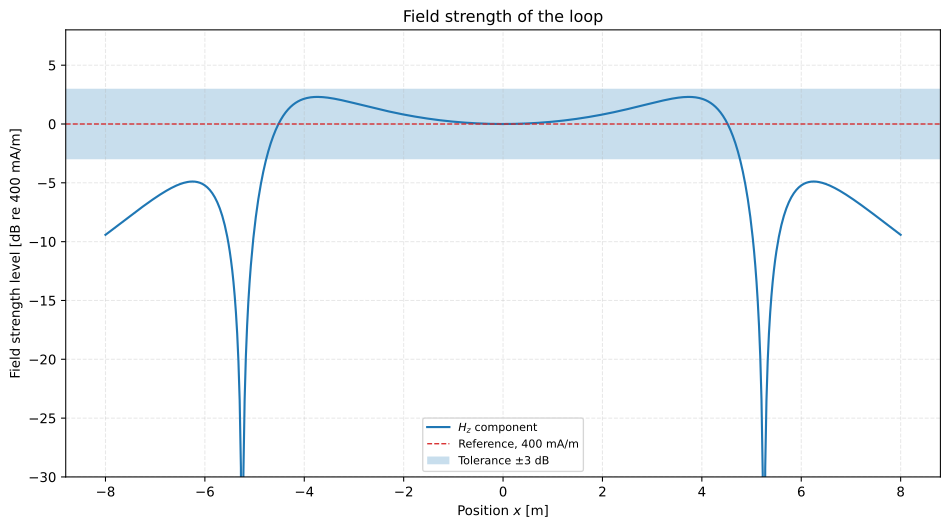
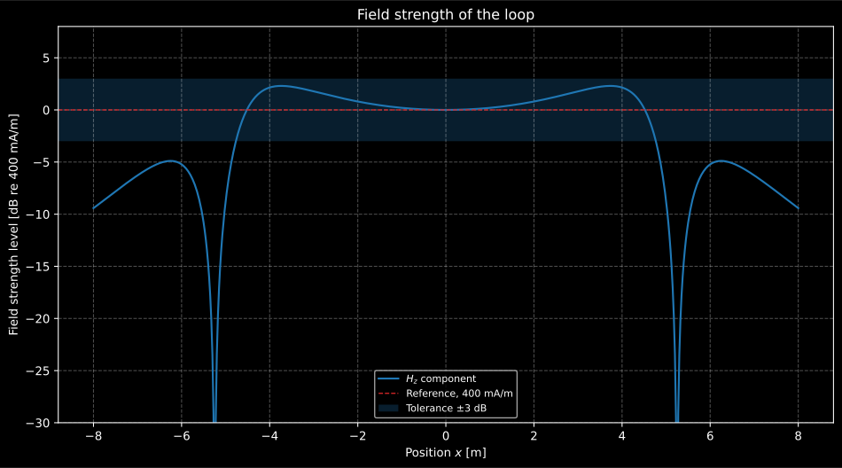
The vertical field across the loop at listening height. Inside, it stays within ±3 dB out to 4.75 m of the 5 m half-width; just above each conductor the field turns horizontal and the vertical component a telecoil reads vanishes, and outside the loop it comes back with the opposite sign. That is the spill a neighbouring room hears, and the reason the useful volume stops short of the walls.
Show the code for this figure
import matplotlib.pyplot as plt
x = np.linspace(-8.0, 8.0, 641)field = electroacoustics.rectangular_loop_field(current, 10.0, 14.0, x, 0.0, 1.2)ax = field.plot()ax.set_ylim(-30.0, 8.0)plt.show()
3. The loop as a load (IEC 62489-1 Annex B, IEC 60118-4 E.3)
Section titled “3. The loop as a load (IEC 62489-1 Annex B, IEC 60118-4 E.3)”The loop is a resistance in series with an inductance (IEC 62489-1 5.4.3.2, B.2). The resistance is for a conductor of length and area , with the resistivity of standard annealed copper, 1/58 Ω·mm²/m at 20 °C and 0.00393 per degree (IEC 60028). The inductance of a rectangle of round wire is Grover’s Formula (58); for turns it is multiplied by , the perfect coupling Table B.1 assumes. The magnitude of the impedance, , is times the resistance at the corner frequency , “1.4 times” in IEC 60118-4 E.3, and the voltage the amplifier has to deliver for a current is .
Table B.1 of IEC 62489-1 is the oracle. Its resistances all come out of the 20 °C resistivity with the perimeter of each loop, and four of its six inductances out of Formula (58) without the term for the flux inside the wire:
| Loop | Size [m] | Turns | Area [mm²] | printed / computed [Ω] | printed / computed [µH] | at 2 kHz, 5 kHz [Ω] |
|---|---|---|---|---|---|---|
| Neck loop | 0.22 diameter | 10 | 0.5 | 0.24 / 0.238 | 85 / not reproduced | 1.09, 2.67 / 1.09, 2.68 |
| Counter loop | 0.35 × 0.45 | 10 | 0.75 | 0.37 / 0.368 | 189 / 189.4 | 2.41, 5.96 / 2.40, 5.95 |
| Home loop | 3 × 4 | 1 | 1.0 | 0.24 / 0.241 | 22 / 22.2 | 0.37, 0.74 / 0.37, 0.73 |
| Small room | 6 × 8 | 1 | 1.5 | 0.32 / 0.322 | 47 / 47.2 | 0.67, 1.52 / 0.67, 1.51 |
| Typical place of worship | 10 × 20 | 1 | 1.5 | 0.69 / 0.690 | 109 / 109.2 | 1.54, 3.50 / 1.53, 3.49 |
| Large place of worship | 15 × 40 | 1 | 2.5 | 0.76 / 0.759 | 218 / not reproduced | 2.85, 6.89 / 2.84, 6.89 |
The impedances are computed from the printed and . The counter loop’s
resistance needs the 1.6 m its sides give, not the 1.5 m the table prints for
its perimeter, which is an erratum. Table B.1 does not say which formula it
used for the inductance, and no reading of the wire size reaches the neck
loop’s 85 µH or the large loop’s 218 µH, so those two are not claimed.
rectangular_loop_inductance keeps the internal term by default, 2.7 % to
4.2 % more on these four loops, because at audio frequencies the skin depth in copper (2 mm at 1 kHz)
exceeds the radius of every conductor in the table: pass
internal_inductance=False to reproduce Table B.1. IEC 60118-4 E.3 offers a
rule of thumb for a single-turn square loop of side over a square metre,
µH, and it reads high: for 1.5 mm² wire Formula (58) gives µH
for a 5 m square and µH for a 20 m one.
r = electroacoustics.loop_resistance(60.0, 1.5) # typical place of worshipl = electroacoustics.rectangular_loop_inductance(10.0, 20.0, 1.5, internal_inductance=False)z = electroacoustics.loop_impedance(r, l)print(round(r, 3), round(l * 1e6, 1)) # 0.69 ohm 109.2 µHprint(round(z.corner_frequency_hz)) # 1005 Hzprint(z.at([2000.0, 5000.0]).round(2)) # [1.54 3.5 ] ohmprint(round(electroacoustics.rectangular_loop_inductance(10.0, 20.0, 1.5) * 1e6, 1)) # 112.2 µHprint(round(electroacoustics.loop_resistance(60.0, 1.5, conductor_temperature_c=40.0), 3)) # 0.744 ohmAbove its corner frequency the loop’s impedance rises 6 dB per octave, so a voltage-driven loop loses its treble. The usual cure is a current-drive amplifier, whose output resistance, some ten times the loop’s, keeps the current constant while the impedance varies (E.3); the price is voltage, and the overload test of section 7 is where it is paid.
4. Test signals and the meter (IEC 60118-4 6.1, 6.4, 6.6)
Section titled “4. Test signals and the meter (IEC 60118-4 6.1, 6.4, 6.6)”The field strength meter is a sound level meter with a magnetic pick-up coil in
place of the microphone, equalized flat within ±1 dB from 50 Hz to 10 kHz, with
a true-RMS detector and the 125 ms averaging of its “F” mode (6.1.3); the peak
programme meter of 6.1.4 is the alternative, and in case of doubt the true-RMS
reading is definitive (6.1.1). field_strength_meter reads a record flat or
A-weighted, the latter for the noise measurements of clause 7 and 10.4.
The pink noise of 6.4 is band-limited by third-order Butterworth filters at
75 Hz and 6.5 kHz and has a peak-to-peak to RMS ratio of at least 18 dB, a
crest factor of 4; IEC 62489-1 5.4.8.2 b) asks the same signal for 18 dB
±2 dB. Gaussian noise reaches about 5.5 times its RMS in a minute at 48 kHz,
21 dB peak to peak, which meets the first and fails the second, so
loop_test_noise clips at 4 times the RMS and rescales, which meets both.
The combi signal of 6.6 and Table 2 interleaves 1 kHz tone bursts of at
least 1 s, with 5 ms ramps, with at least four times as much of that noise
6 dB lower: the sine’s peaks sit 3 dB below the noise’s, and the amplifier runs
cooler than on a steady sine while the level can still be read on the bursts.
fs = 48000print(electroacoustics.band_limit_response([100.0, 5000.0]).round(2))  # [-0.71 -0.82] dBnoise = electroacoustics.loop_test_noise(fs, 30.0, seed=7)print(round(20 * np.log10(np.ptp(noise) / np.sqrt(np.mean(noise**2))), 2))  # 18.06 dB
combi = 0.4 * electroacoustics.combi_signal(fs, cycles=2, seed=7)  # sine bursts at 400 mA/mreading = electroacoustics.field_strength_meter(combi, fs)print(round(reading.maximum_db, 2), round(reading.equivalent_db, 2))  # 0.0 -3.98 dB
6.4 NOTE 2, and NOTE 3 to 5.4.8.2 of IEC 62489-1, print the theoretical responses of the band-limiting filters as −0.8 dB at 100 Hz and −0.7 dB at 5 kHz. The two filters give −0.71 dB and −0.82 dB, the other way round; the ±1 dB flatness the note explains holds either way. The clause itself asks for “at least one-third-order” filters, a slip for the third order its B.2.3, its own NOTE 2 and IEC 62489-1 all name; both are in the errata register.
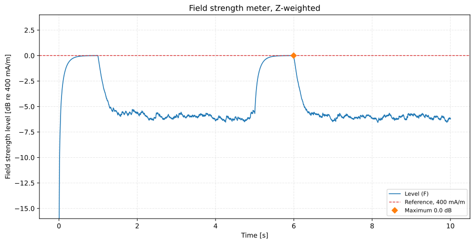
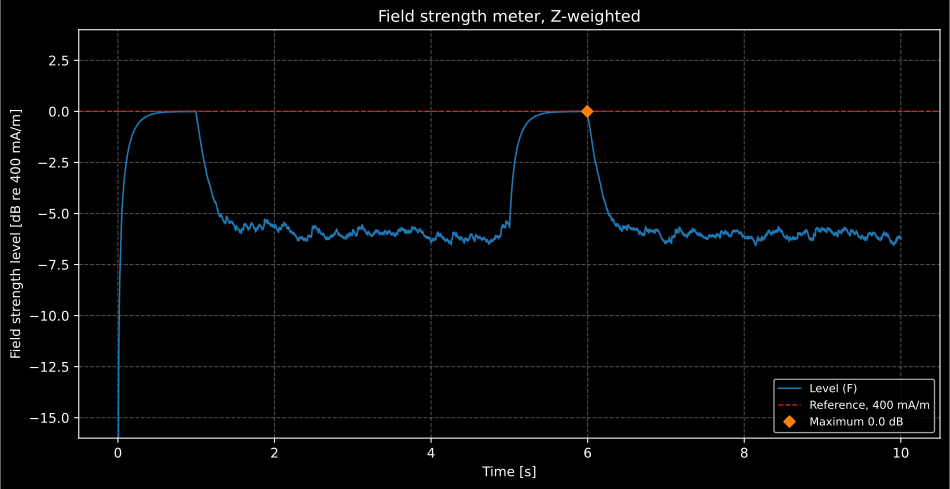
The meter on the combi signal. The bursts read 0 dB, the noise 6 dB less, and the maximum indication, which 8.2.7 reads, is the sine’s; the level of the whole record is 4 dB down, which is what spares the amplifier.
Show the code for this figure
ax = reading.plot()ax.set_ylim(-16.0, 4.0)plt.show()5. How the measurement goes (IEC 60118-4 clauses 7 to 10)
Section titled “5. How the measurement goes (IEC 60118-4 clauses 7 to 10)”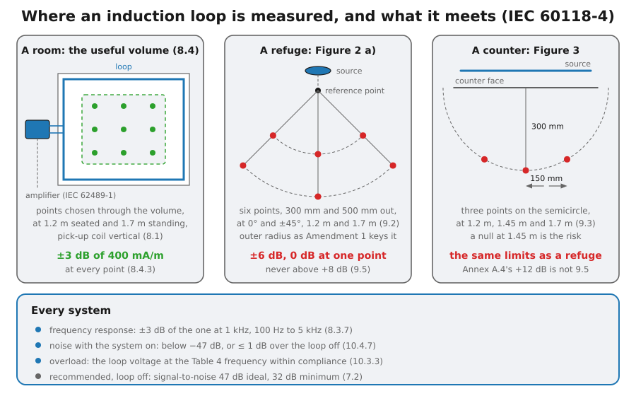
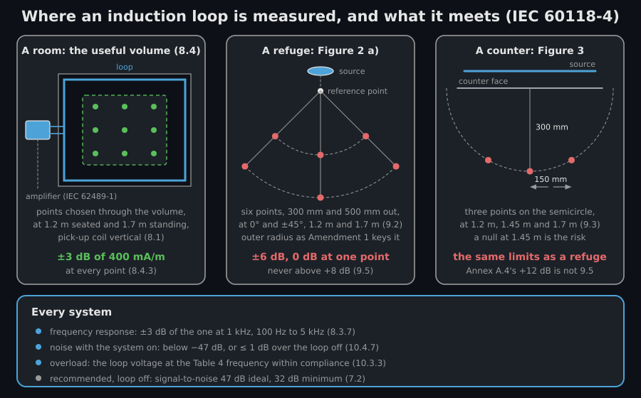
- The site first, loop off (7.1). Everything else normally in use is on and dimmable lighting half-dimmed; the magnetic background noise is read A-weighted at enough points of the intended volume, at 1.2 m for seated and 1.7 m for standing listeners, and it is worth listening to as well, because its spectrum decides how disturbing it is.
- Set the level (8.2). With a 1 kHz sine, or the combi signal, and the true-RMS meter, the amplifier’s controls are set so that the field reaches 400 mA/m; with speech or pink noise the target is the reading the manufacturer states for 400 mA/m (Table 3 gives −6 dB for pink noise on the RMS meter). A warm-up of 10 min comes first, and the AGC’s release time is waited out after every change of input level.
- Survey the field and the response (8.3, 8.4). The level at the selected points of the useful volume, and the frequency response at 100 Hz, 1 kHz and 5 kHz at least, starting with 5 kHz, where metal in the building shows first.
- The noise with the system on (10.4), all inputs muted, A-weighted at the same points as the background noise, so the two can be compared point by point.
- The overload test (10.3) at the frequency Table 4 gives for the programme, then the commissioning with sound sources in their normal places and, where possible, a few hearing-aid users present (10.1).
6. The site and the installed system (IEC 60118-4 7.2, 8.3.7, 8.4.3, 10.4.7)
Section titled “6. The site and the installed system (IEC 60118-4 7.2, 8.3.7, 8.4.3, 10.4.7)”The difference between the 0 dB reference and the A-weighted background noise
is the reference signal-to-noise ratio of 7.2. Above 47 dB is the ideal,
for theatres and wherever the aesthetic value of speech matters; 32 dB is the
recommended minimum, and a lower ratio “shall be reported and agreed with the
system operator”; as low as 22 dB may be tolerable for short periods, where the
noise “has no significant undesirable tonal quality or is mostly at low
frequencies”. These are recommendations, and assess_background_noise classes
the site at its noisiest point without folding the class into a verdict;
noise_is_tonal=True, there and in verify_induction_loop_system, withholds
the 22 dB relaxation from a noise with an undesirable tonal quality.
The requirements of the installed system are four. The maximum field is
400 mA/m at one point at least of the useful volume (8.2.1, 8.2.7), and
every selected point is within ±3 dB of that specified level (8.4.3); the
frequency response is within ±3 dB of the response at 1 kHz from 100 Hz to
5 kHz at every point (8.3.7); and the noise with the system switched on is
below −47 dB where the site’s ratio is above 47 dB, otherwise no more than
1 dB above the loop-off level at the same point (10.4.7 as amended, which
was 10.2.7). The two sentences of 10.4.7 say “greater than 47 dB” and “less
than 47 dB”, so a ratio of exactly 47 dB falls in neither; the 1 dB rule is
applied there, and the gap is in the errata register.
verify_induction_loop_system judges each requirement it is given on every
value it covers, and returns one verdict object.
current = electroacoustics.loop_current(10.0, 20.0, height_m=1.2)   # the typical place of worshipx, y = np.meshgrid([-3.5, 0.0, 3.5], [-8.0, -4.0, 0.0, 4.0, 8.0])     # fifteen seatslevels = np.stack([    electroacoustics.rectangular_loop_field(current, 10.0, 20.0, x, y, height).level_db("z")    for height in (1.2, 1.7)])first = electroacoustics.verify_induction_loop_system(levels)print(first.passes, first.failed)                                     # False ('field_strength',)print(round(first.requirement("field_strength").worst_margin_db, 2))  # -1.41 dB, +4.41 at the corners
levels = levels - 2.0          # turned down 2 dB, so the spread straddles 0 dBoff = [-38.5, -36.0, -40.2, -37.1, -35.4]   # loop off, A-weighted, dB re 400 mA/mon = [-38.1, -35.6, -39.9, -36.6, -35.0]    # system on, inputs mutedverdict = electroacoustics.verify_induction_loop_system(    levels,    frequencies_hz=[100.0, 1000.0, 5000.0],    response_db=[[-0.4, 0.0, -1.8], [-0.3, 0.0, -2.4], [-0.6, 0.0, -3.4]],    background_noise_levels_db=off,    system_noise_levels_db=on,)site = verdict.background_noiseprint(round(site.reference_signal_to_noise_ratio_db, 1), site.category)  # 35.4 acceptableprint(verdict.passes, verdict.failed)                                    # False ('frequency_response',)for requirement in verdict.requirements:    print(requirement.name, round(requirement.worst_margin_db, 2))# field_strength 0.56 / field_strength_reached 2.41# frequency_response -0.4 / system_noise 0.5
The first verdict is the lesson of section 2 again: with 400 mA/m set above the centre, the seats near the conductors run 4.4 dB hot, and the cure is to set the level on the spread, not on one point. Turned down 2 dB, the hottest seat still reads 2.4 dB above the reference, which is what 8.2.7 asks: the maximum field reaches 400 mA/m somewhere in the volume. A spread set wholly below the reference, every seat between −3 dB and −0.1 dB, would pass the window of 8.4.3 and fail 8.2.7. The second fails on the far seat at 5 kHz, 3.4 dB down: the loss to metal of Annex F, which the standard gives no model for. Its correction is the response the installer measures and equalizes, and the overload test of section 7 is what checks that the amplifier can afford the lift.
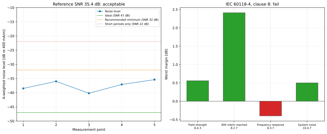
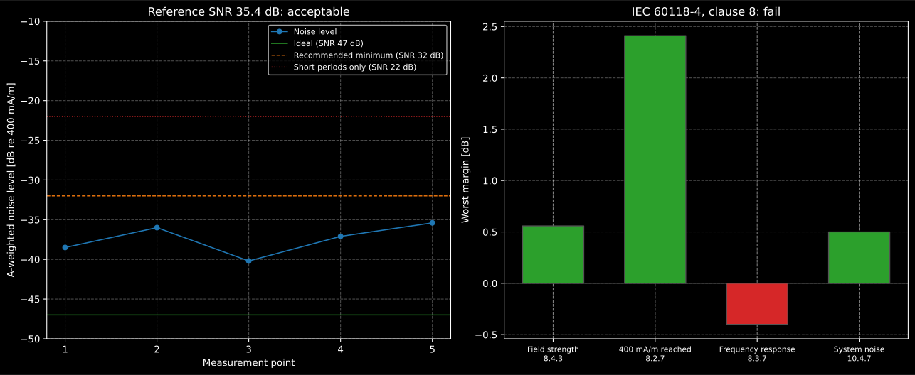
The site is acceptable but not ideal, so the system-on noise is judged on the 1 dB rule, which it meets by half a decibel. The field meets its window once the level is set on the spread; the response does not, at one seat and one frequency, and that is enough to fail the system.
Show the code for this figure
fig, (ax_site, ax_verdict) = plt.subplots(1, 2, figsize=(13.5, 5.6))verdict.background_noise.plot(ax_site)verdict.plot(ax_verdict)plt.show()6.1 A refuge, a call point and a counter (clause 9 as amended)
Section titled “6.1 A refuge, a call point and a counter (clause 9 as amended)”A small system is judged at fixed points instead of over a useful volume. Amendment 1 rewrites clause 9: six points for a disabled refuge or call point, along the perpendicular and ±45° at 300 mm and 500 mm from the reference point (Figure 2 a), or on two rows 424 mm and 700 mm wide for a larger source (Figure 2 b), at 1.2 m and 1.7 m; three points for a counter, on a semicircle of 300 mm radius at its bottom and 150 mm either side (Figure 3), at 1.2 m, 1.45 m and 1.7 m, the middle height because a poorly designed installation may have a null there. At every point the level is within ±6 dB of 400 mA/m and meets 8.3.7, at one point at least it reaches 0 dB, and nowhere where people are expected to stand, which Figure 3 puts outside the semicircle of points, is it above +8 dB (9.5).
points = electroacoustics.small_volume_measurement_points("counter")print(points.shape, points[0, :, :2].round(3).tolist())# (3, 3, 3) [[-0.15, 0.26], [0.0, 0.3], [0.15, 0.26]]  x, y in m; z the height
counter = electroacoustics.verify_small_volume_system(    [[5.1, 4.2, 5.3], [2.0, 1.1, 2.2], [-2.9, -3.8, -2.7]],   # rows at 1.2 m, 1.45 m, 1.7 m    layout="counter",    standing_area_levels_db=[6.5, 7.9, 9.2],   # the standing area beside the semicircle)print(counter.passes, counter.failed)                                    # False ('standing_area',)print(round(counter.requirement("standing_area").worst_margin_db, 2))    # -1.2 dB
The rows of field_strength_levels_db follow the heights of
small_volume_measurement_points, lowest first, so the counter above is
strongest at 1.2 m and weakest at 1.7 m. The informative Annex A.4 allows “up to, but not greater than,
+12 dB” at 1.45 m for a counter and calls the counter’s requirement less
stringent than a refuge’s; 9.5 applies the same limits to both at every
height, and 9.5 is what is applied. Amendment 1 also corrects the key of
Figure 2 a), whose outer radius the 2014 print gave as 200 mm.
By contract, a useful magnetic field volume with representative points of the
installer’s choosing may replace the points of 9.2 or 9.3 (9.4). The same
limits of 9.5 hold at every point, and as a minimum the volume has to meet
them at one position at least at each height of the clause it replaces:
1.2 m and 1.7 m for a refuge, 1.2 m, 1.45 m and 1.7 m for a counter. The
layouts "refuge_useful_volume" and "counter_useful_volume" take the height
of each point, and refuse a set of points that leaves one of those heights
out.
volume = electroacoustics.verify_small_volume_system( [4.6, 3.9, 1.8, 0.7, -2.4, -3.1], layout="counter_useful_volume", heights_m=[1.2, 1.2, 1.45, 1.45, 1.7, 1.7],)print(volume.passes) # True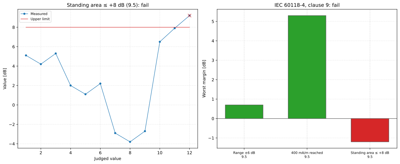
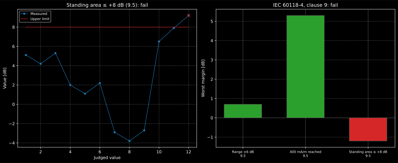
A counter loop that meets its window at all nine points and still fails, because a customer standing beside the semicircle, close to the counter face, reads 9.2 dB. A vertical loop in the counter face makes a strong field close to it by construction, which is what the +8 dB cap and 9.5 NOTE 1 are about.
Show the code for this figure
fig, (ax_area, ax_verdict) = plt.subplots(1, 2, figsize=(13.5, 5.6))counter.requirement("standing_area").plot(ax_area)counter.plot(ax_verdict)plt.show()7. Commissioning and the overload test (IEC 60118-4 10.2, 10.3 as amended)
Section titled “7. Commissioning and the overload test (IEC 60118-4 10.2, 10.3 as amended)”Amendment 1 replaces the 1.6 kHz overload test with one tied to the programme. With a 1 kHz sine set 7 dB below the field required at a point, the voltage across the loop is measured and the frequency raised at the same input until that voltage doubles, or the frequency of Table 4 is reached, whichever is the higher frequency (10.3.2), and no clipping may appear at the frequency of Table 4 and that level (10.3.3):
| Programme | Upper limit of the maximum power bandwidth | Test frequency |
|---|---|---|
| Speech for transient use, for example small-volume systems | 1.25 kHz | 2.5 kHz |
| Speech (default) | 1.6 kHz | 3.15 kHz |
| Music | 2.0 kHz | 4.0 kHz |
The test frequency is about twice the upper limit because a sine at the limit
itself would draw an unrealistically high current from the power supply; the
reduced level at twice the frequency loads it the way real programme does
(10.3.1). Of the three ways the amendment lists to detect clipping, the second
compares the loop voltage with the amplifier’s compliance voltage of
IEC 62489-1, and that one is computable from the loop’s impedance and the
current the amplifier puts into it. The verdict is taken at the Table 4
frequency, where 10.3.3 puts the requirement; when the voltage doubles only
above that frequency, the sweep runs on to the doubling, and the rest of it is
drawn and its highest voltage kept as max_voltage_v, but not judged. Here
the amplifier lifts its current above 1 kHz to make up the metal loss of
section 6:
lift = electroacoustics.amplifier_frequency_response( [100.0, 1000.0, 2000.0, 3150.0, 4000.0, 5000.0, 8000.0], [2.0, 2.0, 2.4, 2.9, 3.2, 3.5, 3.6], # output current, A)print(lift.response_db.round(2)) # [0. 0. 1.58 3.23 4.08 4.86 5.11] dB re 1 kHzspeech = electroacoustics.verify_amplifier_overload(current, z, 11.0, current_response=lift)print(round(speech.test_current_a, 2), round(speech.doubling_frequency_hz)) # 2.65 A 2091 Hzprint(round(speech.end_frequency_hz), round(speech.test_frequency_voltage_v, 2), speech.passes) # 3150 8.71 Truemusic = electroacoustics.verify_amplifier_overload( current, z, 11.0, programme="music", current_response=lift)print(round(music.test_frequency_voltage_v, 2), round(music.headroom_db, 2), music.passes) # 11.99 -0.75 FalseThe voltage doubles at 2.1 kHz, below the Table 4 frequency in both cases, so the sweep runs on to 3.15 kHz for speech and to 4 kHz for music. The amplifier that serves speech with 2 dB to spare clips on music: at 4 kHz the loop wants 12 V and the amplifier has 11 V. That is the trade the equalization of section 6 made, and it is why a correction for metal loss is decided together with the amplifier and not after it.
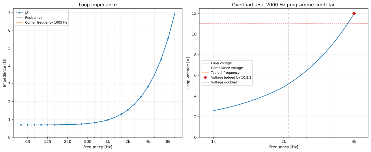
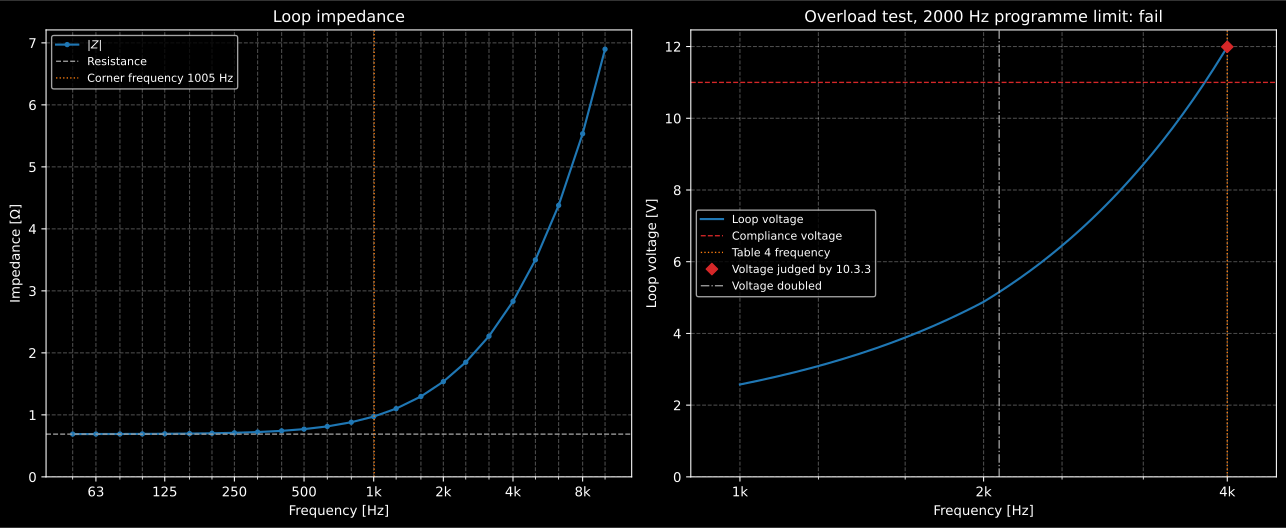
The loop as a load, and the overload sweep for music. The rise of the impedance above the corner and the lift of the current multiply, and the crossing with the compliance voltage lies just inside the sweep.
Show the code for this figure
fig, (ax_z, ax_sweep) = plt.subplots(1, 2, figsize=(13.5, 5.6))z.plot(ax_z)music.plot(ax_sweep)plt.show()8. The amplifier (IEC 62489-1 clause 5)
Section titled “8. The amplifier (IEC 62489-1 clause 5)”IEC 62489-1 lists what an amplifier’s specification states. The rated conditions (5.4.1 to 5.4.6) are declared, not measured; standard measuring conditions put the output current 10 dB below the rated one (5.2.2). The measured characteristics that are computations are these:
- Maximum (distortion-limited) output current (5.4.7): from standard measuring conditions the 1 kHz load current is raised until the total harmonic distortion across the resistive part of the load reaches the rated value, and the current is the total voltage across that resistance over its value. It has to be deliverable for at least 10 s, a condition on the measurement rather than a computation.
- Compliance voltage (5.4.8): the maximum positive-going and negative-going peak voltages across the rated load, over at least 60 s of the specified pink noise with the AGC fully in operation, averaged and divided by : the RMS voltage of the sine with the same peaks.
- Noise (5.4.9): the equivalent input noise voltage , the 1 kHz input that gives the same current as the noise, or the signal-to-noise ratio dB.
- Frequency response (5.4.12): the load current at one-third-octave centres from at least 50 Hz to 8 kHz, 0 dB at 1 kHz.
- Automatic gain control (5.4.13): the steady-state output current against the source e.m.f.; Amendment 1 adds the recommendation of an input range of at least 32 dB for an output change of at most 3 dB (5.4.13.4).
- Quadrature phase error (5.4.14): two adjacent loops fed about 90° apart make a rotating field instead of nulls; the characteristic is the maximum deviation from 90° over 100 Hz to 5 kHz.
steps = electroacoustics.maximum_output_current(    [2.0, 3.0, 4.0, 4.5, 5.0],            # V across the 0.69 ohm of the rated load    [0.05, 0.08, 0.3, 1.2, 4.0],          # THD there, %    load_resistance_ohm=0.69,    rated_thd_percent=1.0,)print(round(steps.maximum_current_a, 2))  # 6.36 A where the THD reaches 1 %
load = np.clip(4.5 * electroacoustics.loop_test_noise(fs, 60.0, seed=3), -14.0, 14.0)print(round(electroacoustics.compliance_voltage(load), 2))    # 9.9 V: clipping at ±14 Vprint(round(electroacoustics.equivalent_input_noise_voltage(0.1, 1.6, 0.00032) * 1e6, 1))  # 20.0 µVprint(round(electroacoustics.amplifier_signal_to_noise_ratio(5.0, 0.00032), 1))            # 83.9 dB
emf = np.arange(-60.0, 1.0, 5.0)                                   # source e.m.f., dBoutput = np.where(emf < -40.0, emf + 30.0, -10.0 + 2.5 * (emf + 40.0) / 40.0)agc = electroacoustics.agc_characteristic(emf, output)print(round(agc.agc_range_db, 1), agc.recommended_range_db)        # 40.5 32.0 dB
f = np.array([100.0, 125, 160, 200, 250, 315, 400, 500, 630, 800, 1000]             + [1250, 1600, 2000, 2500, 3150, 4000, 5000])phase = 90.0 - 4.0 * np.log2(f / 700.0) ** 2 / 3.0                 # degrees between the currentsquadrature = electroacoustics.quadrature_phase_error(f, phase)print(round(quadrature.max_deviation_deg, 2), quadrature.max_deviation_frequency_hz)  # 10.73 5000.0print(round(quadrature.level_increase_db, 2), round(quadrature.level_decrease_db, 2))  # 1.48 -1.79 dB
A deviation from 90° leaves an in-phase component of one field against the other, which raises the level by where the two add and lowers it by where they subtract. 5.4.14.1 gives the example of 85°, an in-phase part of 0.087, and prints the change as “increased or decreased by 0.72 dB”; the rise is 0.72 dB, the fall 0.79 dB.
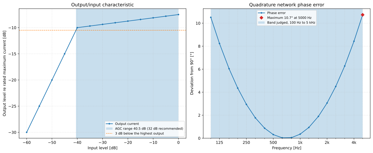
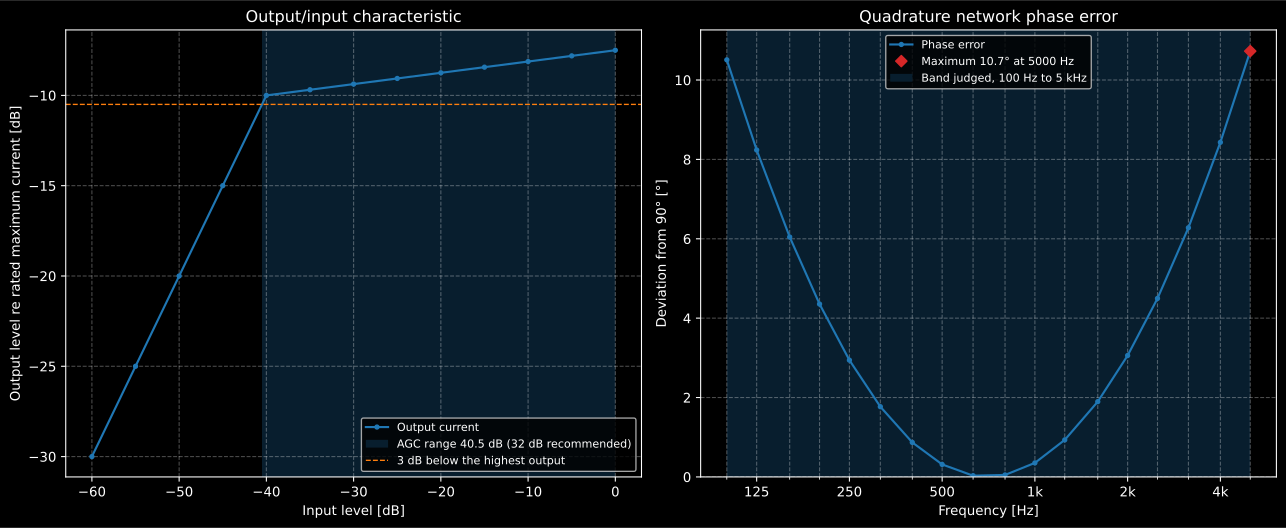
The amplifier’s AGC holds its output within 3 dB over 40.5 dB of input, 8.5 dB more than 5.4.13.4 recommends; the quadrature network is within 11° of quadrature over the speech band, a rise of 1.5 dB and a fall of 1.8 dB where the two loops’ fields meet.
Show the code for this figure
fig, (ax_agc, ax_phase) = plt.subplots(1, 2, figsize=(13.5, 5.6))agc.plot(ax_agc)quadrature.plot(ax_phase)plt.show()9. The neck loop (IEC 62489-1 clause 9 and the draft Amendment 2)
Section titled “9. The neck loop (IEC 62489-1 clause 9 and the draft Amendment 2)”A neck loop is a small loop, often about 230 mm across, worn round the neck and fed from a phone, a music player or a larger piece of equipment. Clause 9, added by Amendment 1, specifies it on the non-metallic jig of Annex E, with the field measured at the telecoil position by a small inductor about 3 mm by 10 mm, the size of a behind-the-ear telecoil: the input voltage that produces 400 mA/m at 1 kHz (9.1), the smallest magnitude of the input impedance over 100 Hz to 5 kHz rounded to the nearest ohm (9.2.1), and the frequency response, stated in text as the frequencies where it differs from the one at 1 kHz by 3 dB (9.3.3). A passive loop is linear, so the voltage for 400 mA/m follows from a level measured at any voltage.
The draft Amendment 2 (prEN 62489-1:2010/prA2:2017, a draft for comment and cited as one) replaces Annex D with two example specifications: type 1, “Suitable for audio sources powered by two primary 1,5 V cells and higher voltage supplies”, with a DC resistance of 32 Ω ±5 %, and type 2, “Neck loops with transformer or amplifier”, with an input DC resistance of at least 32 Ω, both reaching 400 mA/m on the jig with at most 1.06 V at the input.
f = np.array([100.0, 200, 500, 1000, 2000, 5000, 8000, 10000])z_in = np.abs(32.2 + 2j * np.pi * f * 0.53e-3) # 32.2 ohm and 0.53 mH, about 25 turnslevel = -6.0 + 20 * np.log10(z_in[3] / z_in) # -6 dB at 1 kHz with 0.5 V appliedneck = electroacoustics.neck_loop_characteristics(f, level, z_in, input_voltage_v=0.5)print(round(neck.reference_input_voltage_v, 3), neck.minimum_impedance_ohm) # 0.998 V 32.0 ohmprint([round(v) for v in neck.frequencies_3db_hz]) # [9723] Hzdraft = electroacoustics.verify_neck_loop(32.4, neck.reference_input_voltage_v, neck_loop_type=1)print(draft.passes, draft.resistance_passes, draft.voltage_passes) # True True TrueThe draft’s Table D.1, the field a type 1 loop reaches from a 3 V and a 9 V battery, rests on a model of the source it does not give, and is not reproduced.
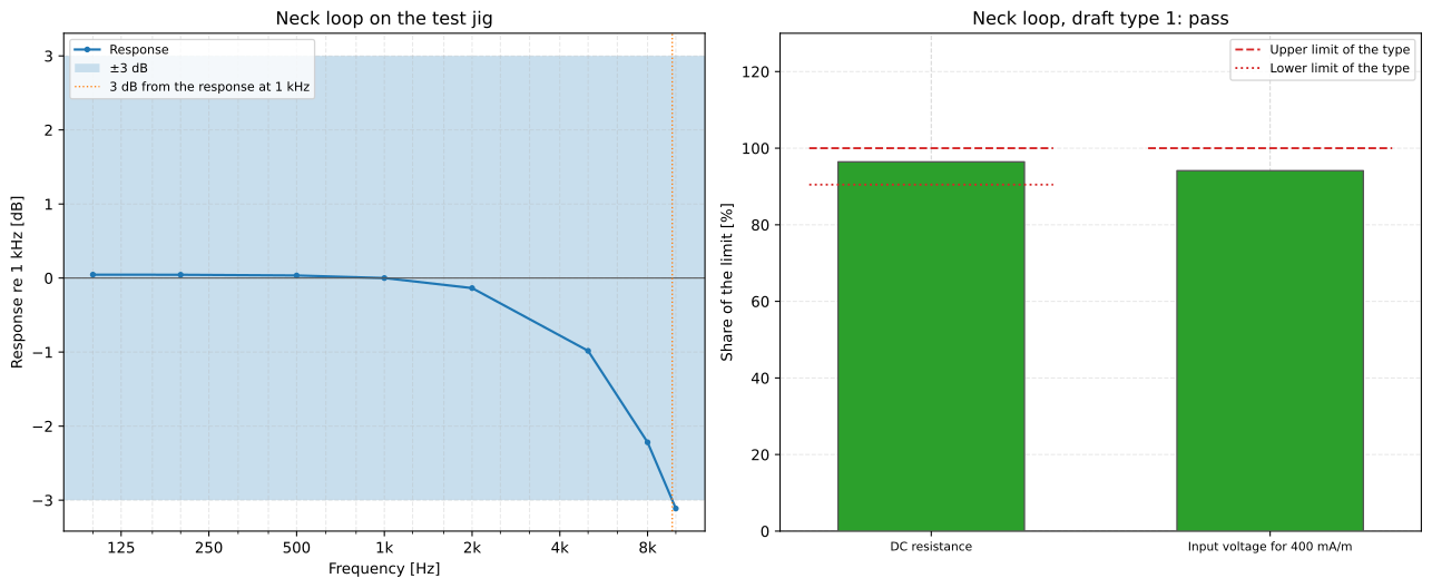
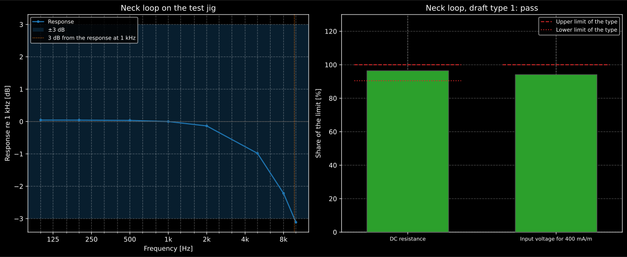
The loop’s inductance, not its field, sets the response of a voltage-driven neck loop: 0.53 mH against 32 Ω puts the corner near 9.7 kHz, well above the 5 kHz of the system requirements.
Show the code for this figure
fig, (ax_response, ax_verdict) = plt.subplots(1, 2, figsize=(13.5, 5.6))neck.plot(ax_response)draft.plot(ax_verdict)plt.show()What this guide covers
Section titled “What this guide covers”Covered
IEC 60118-4:2014 with its Amendment 1:2017: the 400 mA/m reference and its levels (3.1, 4.3), the flux density and the telecoil’s cosine law (E.6, E.2), the true-RMS meter flat or A-weighted (6.1.3), the band-limited pink noise with its crest factor (6.4) and the combi signal (6.6, Table 2), the background noise classes of 7.2, the verdict on a system over its useful magnetic field volume (8.2.7, 8.3.7, 8.4.3, 10.4.7), the measurement points and the verdict of a refuge, call point or counter as the amendment writes clause 9, at the points of Figures 2 and 3 or of a useful volume that covers their heights (9.4, 9.5), and the overload test of 10.3 with Table 4, judged on the compliance voltage at the Table 4 frequency (10.3.3). The loop’s field by Biot-Savart at any point, which reproduces the centre formula of E.1 and the curves of Figure E.2 b), and the current and loop size of IEC 62489-1 5.4.10 and 5.4.11, which reproduce the currents of Figure H.1. The loop as a load (IEC 62489-1 Annex B): the resistance with the IEC 60028 resistivity and the inductance by Grover’s Formula (58), which reproduce Table B.1 as shown. The amplifier’s maximum output current, compliance voltage, noise, frequency response, AGC range and quadrature phase error (5.4.7, 5.4.8, 5.4.9, 5.4.12, 5.4.13, 5.4.14), and the neck loop’s characteristics (clause 9) with the two types of the draft Amendment 2, cited as a draft.
Not covered
The effect of metal in the building (Annex F) has no model in the standard and none here: it is the frequency response the installer measures. The peak programme meter of 6.1.4, the speech signals of 6.3 (ISTS, ITU-T P.50) and the subjective commissioning of 10.1 are not computations. The loop listener and assistive listening device of IEC 62489-1 Annex F, and the monitoring devices, are specified by single values to be met; the draft’s Table D.1 rests on a source model it does not give. The inductances of Table B.1’s neck loop and large loop are not reproduced by any formula tried. The field patterns of Figures E.3 to E.5 and A.1 are of the kind
rectangular_loop_fieldcomputes and are not checked point by point. The 10 s for which 5.4.7 asks the maximum current to be held is a condition on the measurement. The electromagnetic exposure of IEC 62489-2 is outside this library.
References
Section titled “References”- Grover, F. W. (1946). Inductance calculations: Working formulas and tables. D. Van Nostrand. Formula (58), the inductance of a rectangle of round wire (pp. 60-61; read in the 1973 Instrument Society of America edition), which without its internal term reproduces four of the six inductances of Table B.1 of IEC 62489-1.
- International Electrotechnical Commission. (1925). International standard of resistance for copper (IEC 60028:1925). The resistivity of standard annealed copper, 1/58 ohm square millimetre per metre at 20 °C, and its temperature coefficient of 0.00393 per degree (clause I), which reproduce the resistances of Table B.1.
- International Electrotechnical Commission. (2014). Audio-frequency induction-loop systems for assisted hearing – Part 1: Methods of measuring and specifying the performance of system components (IEC 62489-1:2010+AMD1:2014). Read in the consolidated BS EN 62489-1:2010+A1:2015. The amplifier's maximum output current (5.4.7), compliance voltage (5.4.8), noise (5.4.9), field strength and loop dimensions (5.4.10, 5.4.11), frequency response (5.4.12), automatic gain control (5.4.13) and quadrature phase error (5.4.14), the loop's resistance, inductance and impedance (Annex B, Table B.1) and the neck loop (clause 9, Annex E).
- International Electrotechnical Commission. (2014). Electroacoustics – Hearing aids – Part 4: Induction-loop systems for hearing aid purposes – System performance requirements (IEC 60118-4:2014). Read in BS EN 60118-4:2015, which is IEC 60118-4:2014 unchanged. The reference magnetic field strength (3.1), the meters and test signals (6.1, 6.4, 6.6, Table 2), the magnetic background noise (7.2), the maximum field (8.2.7), the frequency response and the useful magnetic field volume (8.3.7, 8.4.3), Annex E: the centre field of a square loop (E.1), the field patterns of Figure E.2, the telecoil's directional response (E.2), the loop impedance (E.3) and the magnetic units (E.6), and the loop currents of Figure H.1.
- International Electrotechnical Commission. (2017). Audio-frequency induction-loop systems for assisted hearing – Part 1: Methods of measuring and specifying the performance of system components – Amendment 2 (draft) (E DIN EN 62489-1/A2:2017-10). The draft prEN 62489-1:2010/prA2:2017 in its German edition, a draft for comment and cited as one. Its Annex D specifies two neck-loop types: type 1, for audio sources powered by two primary 1.5 V cells and higher voltage supplies, 32 ohm plus or minus 5 %, and type 2, with a transformer or an amplifier, at least 32 ohm, both reaching 400 mA/m on the jig with at most 1.06 V.
- International Electrotechnical Commission. (2017). Electroacoustics – Hearing aids – Part 4: Induction-loop systems for hearing aid purposes – System performance requirements – Amendment 1 (IEC 60118-4:2014/AMD1:2017). Read in its Spanish edition, UNE-EN IEC 60118-4:2016/A1:2018. It replaces clauses 9 and 10: the measurement points of a refuge and a counter (Figures 2 and 3), the useful volume that may replace them (9.4) and their limits (9.5), the commissioning window (10.2), the overload test at the frequency of Table 4 (10.3) and the noise with the system switched on (10.4.7).